Home > Miata Tech > First Generation (NA) Tech > NA Steering Wheel Replacement
Steering Wheel Replacement
Submitted by "Voodoo" Bob Krueger
Installing A Non-Airbag Aftermarket Steering Wheel In The Miata
The following is an edited compilation of various bits of information that I saved over the past few years from online sources such as CompuServe's Miataville and the Internet Miata mail list.
I have personally, and successfully, participated in a number of these modifications that were done according to these instructions without incident. I know this method will work if done as described...at least on my and other Miatas of vintage 1990-1993 [on later cars, you may need to insert a 3 ohm (1/4 watt) resistor between the two airbag wires to fool the computer into thinking an airbag is present so that it will turn off the dash indicator light]. Anything you decide to do to your car is, however, your decision and your responsibility, not mine...which is only as it should be. I just wanted to make that clear up front.
 You start with a hub adapter for the Mazda 323 from any Momo or Nardi (or whichever wheel you want) supplier. The Momo part number of their adapter is 5702. You start with a hub adapter for the Mazda 323 from any Momo or Nardi (or whichever wheel you want) supplier. The Momo part number of their adapter is 5702.
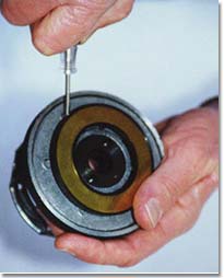
The Momo hub adapter has a contact slider ring on its back side that is meant to mate with a horn circuit contact inside the clock spring assembly on a 323. This ring is encased in plastic and merely pressed onto the back of the hub with a friction fit. The ring is NOT used in the Miata installation. Just take a small screwdriver and insert it under the edge of the plastic piece. That piece, with the horn contact ring and horn wire, will easily separate from the rest of the hub adapter.
- Park your Miata with the wheels as straight as possible.
- Disconnect the NEGATIVE battery terminal (10mm socket). Leave the battery disconnected for 15-20 minutes before proceeding to allow the backup power source to the airbag to discharge.
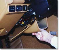
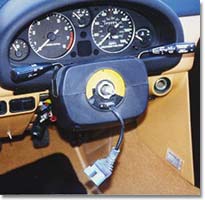
- Remove the access panel from the bottom of the dash immediately beneath the steering wheel and set it aside (2 phillips screws on the lower edge).
- Disconnect the clock spring connectors. These connectors will be found tucked deep down in the wiring beneath the access panel that was removed in the last step. There is a large blue one and a large orange one. The orange connector must be removed first by pressing down on the tab on its side while pulling it apart from the blue connector to which it is attached. You may find that you will need the assistance of a flat-bladed screwdriver to provide the necessary leverage to disconnect the orange one. Once the orange connector has been disconnected, the tab of the blue one can be accessed. Press inward on this tab and pull on the blue connector to free it from its base.
-
- Undo the four 10mm nuts on the back of the steering wheel that hold the airbag to the wheel. Lift the airbag module away from the wheel. You will notice that it has a tether attached between it and the steering wheel. Remove this tether from the steering wheel. Unclip and disconnect the orange and blue connectors which are held by a clip to the left side of the steering wheel's back shroud (underneath the airbag). Put the airbag module aside.
CAUTION: When carrying a live airbag module, make sure the trim cover is pointed away from you to prevent possible injury in the case of an accidental deployment. When placing a live airbag module on any surface, always face the trim cover upward to minimize the movement of the module should it accidentally deploy.
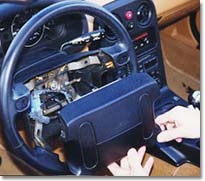
- Center the steering wheel (if you haven't already) and mark the flat end of the steering column shaft, using a felt marker, at top dead center. This will make it easy to see where the straight ahead position is once the wheel has been removed. Remove the 21mm hub nut.
- Remove the wheel with a gentle rocking motion as you pull it toward you. It may take a little persuasion to get it to "pop", but once it does, it should be smooth sailing from there.
 Once the steering wheel has been removed, the clock spring assembly and turn signal canceling ring will be exposed. Note the position of the assembly and the two protruding nylon "points" that are used to cancel the turn signals. These two protrusions should be at the 12 and 6 o'clock positions when the wheels are pointing straight ahead. There is also a marker at the 12 o'clock position on the ring. Try not to disturb the position of this assembly more than is absolutely necessary. Rotating it somewhat during the trimming of the clockspring connector through which the airbag and horn wires pass (riveted to the assembly at 6 o'clock on its face) is inevitable, but don't let it rotate more than necessary or it may be difficult to re-center it so that the turn signals will work properly. If you move it, put it back straight as often as is required to keep it from rotating too far. Directions for re-centering the assembly, should it get out of whack, are on the unit. Once the steering wheel has been removed, the clock spring assembly and turn signal canceling ring will be exposed. Note the position of the assembly and the two protruding nylon "points" that are used to cancel the turn signals. These two protrusions should be at the 12 and 6 o'clock positions when the wheels are pointing straight ahead. There is also a marker at the 12 o'clock position on the ring. Try not to disturb the position of this assembly more than is absolutely necessary. Rotating it somewhat during the trimming of the clockspring connector through which the airbag and horn wires pass (riveted to the assembly at 6 o'clock on its face) is inevitable, but don't let it rotate more than necessary or it may be difficult to re-center it so that the turn signals will work properly. If you move it, put it back straight as often as is required to keep it from rotating too far. Directions for re-centering the assembly, should it get out of whack, are on the unit.
There are three wires coming from the clockspring assembly at the bottom center of the steering hub. Two of these wires go to the blue airbag module connector (the same two you will eventually crimp together) and the other wire is the +12v to the orange horn connector, to which you will add a spade connector and connect to one of the male spade lugs on the back of the MOMO horn button (this wire was green and red striped on my car). It is necessary to cut off the molded plastic connector (that originally went to the airbag module) and slide off the rubber accordion boot before you can do this. Cutting off this connector is the proverbial "point of no return". Well, you can return from here, but things will no longer be cosmetically exactly as they were if you do. Hold your breath, snip the wires at the steering wheel end, and slide the accordion boot off. You want to leave as much wire length intact as possible. The more you have to work with later, the better. Do, however, leave enough wire on the molded connector you removed (airbag end) so that the airbag can be re-installed later if desired. None of us plan to ever sell these cars, but you never know.
HELPFUL NOTE: Get yourself a Dremel tool before starting the next operation. Without a borrowed Dremel tool, I would NEVER have gotten the connector body cut down to size and the extra metal hogged out of the back of the hub adapter. The next day, I went down to Home Depot and bought a Dremel tool of my own for the next time I do this job.
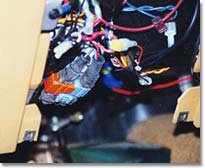
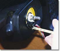 The three wires come out of a rectangular black plastic connector riveted onto the turn signal canceling ring. They are secured with a strain relief tie-wrap. Both the tie-wrap and the plastic protrusion it's tied to need to be cut off. The remaining plastic connector is riveted onto the face of the canceling ring. In order to minimize the amount of metal material that needs to be removed from the back of the adapter hub, it is necessary to shave, file, sand, or cut as much black plastic material from around this 3-wire connector assembly as possible. The idea is to reduce the cross-sectional area of the plastic so as little as possible (width, length, and height) will protrude into the back of the MOMO adapter hub. Lay a towel down in the seat to catch all the little black plastic filings. Lay several towels while you're at it; plastic filings will be flying EVERYWHERE once you start this step. Also roll some masking tape into long, thin, sticky-side-out tubes and lay them along the lower edge of the turn signal canceling ring to prevent small pieces of shaved plastic from getting down into the steering hub area. The plastic connector around the wires is actually a two-piece affair. Use the Dremel tool to cut carefully around the base of the outer piece and remove it. You can then use diagonal cutters to carefully trim away the excess material at the outer edges of the inner piece. BE CAREFUL NOT TO NICK OR SEVER THE WIRES!
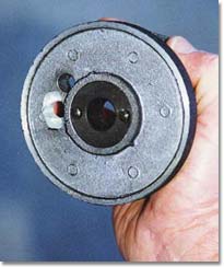 Obviously, not all the plastic can be cut away, hence the need to "hog out" some clearance area on the back of the metal adapter hub. On the back of the adapter hub are two small holes 180 degrees from each other flanking the center splined hole. These engage the two small nylon protrusions on the clock spring assembly. Note that the hub adapter has TOP marked on it. Try to position the hub correctly and align the two small holes with the nylon protrusions. You will see that it will be necessary to use the Dremel tool or some other metal router to carve out a rectangular relief cut in the back of the hub to provide clearance for the remaining portion of the clockspring connector (with the now-unused airbag wires and the horn wire) because not all of the protruding connector can be cut away without endangering the wires. This relief cut needs to be centered immediately below the lower of the two small holes used for the turn signal cancelling protrusions, approximately halfway between the hole and the outside edge of the hub adapter. Finding the correct location to grind away is one of those jobs where two heads are better than one. I strongly recommend that you recruit a friend to share this job with you...to shine a flashlight on the work area if nothing else. Or one of you can hold the adapter more or less in place while the other looks at the backside of the adapter and locates the place where you must start grinding. The hub material is very soft pot metal and grinds relatively easily. Once you locate the proper starting place, you will need to drill a 3/8-inch pass-thru hole in what will eventually be the top center of your new cutout. This will be used to pass the 3 wires through the base of the hub adapter. If you have access to one, It's best to use mount the hub adapter securely in a drill press to accurately drill this hole. The position of the hole will come very close to one the hub "spokes". Be careful when the drill bit is about to penetrate the front side of the hub adapter; do not allow the drill bit to deform or penetrate the hub spoke. Once the pass-thru hole has been drilled, proceed to use a high-speed cutter (a number 117 works really well) in the Dremel tool to hog out the recessed area into which the remaining plastic protrusion will fit.
This whole process will likely take several iterations of removing material and then test-fitting the hub adapter. It is definitely a trial and error procedure to determine exactly what size recess will be required.
- Once the 3/8" pass-through hole for the wires has been drilled and the hub adapter back has been hollowed sufficiently to allow the adapter to slide fully onto the steering column, pass the two airbag wires and the horn wire through the hole and seat the hub adapter on the splines so that the top hole is at the 12 o'clock position immediately opposite the mark you made on the steering column and install the 21mm hub nut. Be sure to encase the wires in some shrink tubing or plastic wire loom material to prevent chafing. The black plastic tubing in which the wires were originally encased works fine for this purpose; trim it to length and re-seat it fully against the bottom of the exposed portion of the wires. Torque the nut to 29-36 ft. lbs. Note that this may or may not be EXACTLY the correct position for the steering wheel to be completely straight once it is installed. Variances in spline positions between the Mazda wheel and the Momo adapter are always possible. Once the new wheel is in place, however, it is a simple matter for any competent alignment shop to re-center the wheel without affecting your alignment by adjusting the tie rod ends equally on both sides.
- Using an appropriately-sized wire nut or butt-end wire connector, splice the two airbag wires together. This will simulate the presence of an airbag to the computer and allow the airbag light on the dash to go out.
NOTE: 1.8-liter cars may require the addition of a 3 ohm resistor between the two airbag wires to simulate the load that an airbag provides to the circuit.
- Connect a spade connector to the "hot" horn wire (green and red in all cars that I have seen thus far). Choose a connector size that matches the spade lug on the back of the new horn button. This wire will be connected to the lug on the back of the horn button.
From here it is mostly a matter of following the (probably pictorial) instructions that came with your steering wheel to make the stack of parts, connect the horn and ground wires to the button, and mount the steering wheel using the six hex-head bolts that came with it.
NOTE: Some Momo horn buttons utilize an integrated ground wire ring that protrudes from the side of the button and articulates with the metal horn button mounting plate. These buttons will not require the use of a separate ground wire from the mounting plate to a spade lug on the button. If the back of your horn button has only one lug, you have this type.
A SUGGESTION: Momo makes a 1/2-inch steering wheel spacer that sells for about $16. This piece is finished in a crinkle black that matches the adapter hub and includes six longer allen-head bolts for attaching it and the steering wheel to the hub. Using this spacer will allow for more room between your fingers and the control stalks, more closely matching the position of the Mazda wheel. I recommend that you contact your Momo dealer and obtain one of these spacers before you start the wheels swap. Believe me, unless your hands are very thin, you'll be glad you did.
Stacking the accordion boot, horn grounding ring, horn button, spacer, and steering wheel properly so that they can be bolted together is another one of those tasks that will make you glad you invited a friend to help you. This part of the job is MUCH easier with one person to hold everything together while the other person gets the bolts started.
- Torque the six allen-head steering wheel bolts to the manufacturer's specification (Momo says 6Nm. I tightened mine until I felt comfortable that the wheel would stay on). Use the same method here that you would for a wheel or cam cover. That is, tighten each bolt a little bit and then do the same to the one that is 180 degrees opposed to it. Move to the next set and do the same. Repeat this process until all six are tight.
Once the wheel is on and tight, re-connect the blue and orange clockspring connectors under the dash, replace the access panel, re-connect the negative lead to the battery, and you're done. Turn on the ignition switch and verify that the air bag light goes out. Honk the horn. If you're as lucky as I was, everything will work as it's supposed to.
Now isn't that better looking than the OEM wheel?
Now you get to reset all your radio stations and the clock...a small price to pay for all that beauty.
Disclaimer
Please note that these tips and pointers are not reviewed or approved by Mazda Motor Corporation or any other corporation or entity other than the originator. The San Diego Miata Club does not accept any liability for damage or injury as a result of utilizing these tips and pointers. Please use common sense and always remember safety first.
|